Fabric definition
This section describes the process of modeling FABulous fabrics in a top-down manner. FABulous can reuse preimplemented tiles which allows it to define fabrics in a LEGO-like manner where it is sufficient to define the Fabric layout in terms of IO and logic tiles or any other required block.
For customization of Tiles or the creation of new blocks, it is possible to model the routing Wires, a central Switch matrix and Primitives
The following figure shows a small fabric, which we will model throughout this section. It provides:
4x IO pins
4x Register file slices
2 DSP block supertiles
4 internal IO ports for coupling the fabric with a CPU

The full model of a fabric is described by the following files:
A file Fabric CSV description providing the Fabric layout, some global settings, and the descriptions of the Tiles-
A set of list files (*.list) desribing the adjacency list of the switch matrix for each of the used tiles or the corresponding adjacency matrix as a CSV file
A set of optional bitstream mapping CSV files
A set of primitives used
The following block provides a fabric.csv example.
FabricBegin      # explained in subsection Fabric layout
NULL,  N_term,   N_term,   N_term,  N_term,  NULL
W_IO,  RegFile,  DSP_top,  LUT4AB,  LUT4AB,  CPU_IO
W_IO,  RegFile,  DSP_bot,  LUT4AB,  LUT4AB,  CPU_IO
...
FabricEnd

ParametersBegin
ConfigBitMode, frame_based        # default is FlipFlopChain
FrameBitsPerRow, 32               # configuration bits per tile row
MaxFramesPerCol, 20               # configuration bits per tile column
Package, use work.my_package.all; # populate package fields in VHDL code generation
GenerateDelayInSwitchMatrix, 80   # we can annotate some delay to multiplexers
MultiplexerStyle, custom          #
ParametersEnd

TILE, LUT4AB      # explained in subsection Tiles
#direction  source_name  X-offset  Y-offset  destination_name  wires
NORTH,      N1BEG,       0,        1,        N1END,            4
...
BEL,      LUT4c_frame_config_OQ.vhdl,  LA_
...
MATRIX,   LUT4AB_switch_matrix.vhdl
EndTILE

TILE, DSP         # all other tiles follow the same scheme
...
Fabric CSV description
For the section between
FabricBeginandFabricEnd, refer to the Fabric layout description.Empty lines will be ignored as well as everything that follows a
#(the comment symbol in all FABulous descriptions).Parameters that relate to the fabric specification are encapsulated between the key words
ParametersBeginandParametersEnd.Parameters that relate to the flow are passed as command line arguments.
Parameters have the format <key>,<value>
FABulous defines the following parameters:
ConfigBitMode,[frame_based|FlipFlopChain]FABulous can write to the configuration bits in a frame-based organisation, similarly to most commercial FPGAs. This supports partial reconfiguration and is (except for in tiny fabrics) superior in any sense (configuration speed, resource cost, power consumption) over flip flop scan chain configuration (the option selected by most other open source FPGA frameworks).
Configuration readback is not currently supported, as it was considered ineffective for embedded FPGA use cases.
FrameBitsPerRow,unsigned_intIn frame-based configuration mode, FABulous will build a configuration frame register over the height of the fabric and provide the specified number of data bits per row. This will generate frame_data wires in the fabric, which correspond to bitlines in a memory organisation.
Note that the specified size corresponds to the width of the parallel configuraton port and 32 bits is the most sensible configuration for most systems.
Currently, we set
FrameBitsPerRowglobally for all rows but we plan to extend this to allow for resource-type specific adjustments in future versions. For instance, the tiles at the north border of a fabric may only provide some fixed U-turn routing without the need of any configuration bits, which could be reflected by removing all frame_data wires in the top row. This extension may include an automatic adjustment mode.MaxFramesPerCol,unsigned_intFor the frame-based configuration mode, this will specify the number of configurations frames a tile may use. The total number of configuration bits usable is:
FrameBitsPerRowxMaxFramesPerColNote that we can leave possible configuration bits unused and that no configuration latches will be generated for unused bits.
FABulous will generate the specified number of vertical frame_strobe wires in the fabric, which correspond to wordlines in memory organisation.
FrameBitsPerRowandMaxFramesPerColshould be around the same number to minimize the wiring resources for driving the configuration bits into the fabric. In most cases, onlyMaxFramesPerColwill be adjusted to a number that can accomodate the number of configuration bits needed.Currently, we set
MaxFramesPerColglobally for all resource types (e.g., LUTs and DSP block columns) but we plan to extend this to allow for resource-type specific adjustments. This feature may include an automatic adjustment mode.Package,stringThis option will populate the package declaration block on VHDL output mode with the string to declare a package.
GenerateDelayInSwitchMatrix,unsigned_intThis option will annotate the specified time in ps to all switch matrix multiplexers. This ignored for synthesis but allows simulation of the fabric in the case of configured loops (e.g., ring-oscillators).
MultiplexerStyle,[custom|TODO]FABulous can generate the switch matrix multiplexers in different styles including behavioral RTL, instantiating standard cell primitives and instantiation of full custom multiplexers.
The latter is implemented by replacing a defined n-input multiplexer with a predefined template. For instance, for the Skywater 130 process, we provide a transmission gate-based custom MUX4. In the case of requiring a MUX16, FABulous will synthesize this multiplexer to use 4 + 1 of our custom cells.
Note
So far, FABulous fabrics use fully (binary) encoded multiplexers (e.g., a MUX16 requires 4 configuration bits). However, the major vendors Xilinx and Intel use highly optimized SRAM cells where a configuration cell may directly control a pass transistor (e.g., as used in Xilinx UltraScale fabrics). For a MUX16, this requires 2 x 4 = 8 configuration bits, but is slightly better in area as omits a decoder. We plan to extend the FABulous switch matrix compiler accordingly.
Fabric layout
FABulous models FPGA fabrics as simple CSV files that describe the fabric layout in terms of Tiles. A tile is the smallest unit in a fabric and typically hosts primitives like a CLB with LUTs or an I/O block. Multiple smaller tiles can be combined into Supertiles. The following figure shows the fabric.csv representation of our example fabric as shown in a spreadsheet program.
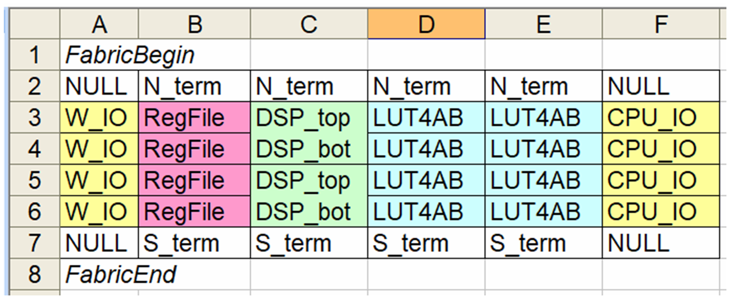
FabricBegin
NULL,  N_term,   N_term,   N_term,  N_term,  NULL
W_IO,  RegFile,  DSP_top,  LUT4AB,  LUT4AB,  CPU_IO
W_IO,  RegFile,  DSP_bot,  LUT4AB,  LUT4AB,  CPU_IO
W_IO,  RegFile,  DSP_top,  LUT4AB,  LUT4AB,  CPU_IO
W_IO,  RegFile,  DSP_bot,  LUT4AB,  LUT4AB,  CPU_IO
NULL,  S_term,   S_term,   S_term,  S_term,  NULL
FabricEnd
The fabric layout is encapsulated between the key words
FabricBeginandFabricEnd.The specified tiles are references to tile descriptors (see Tiles). The tiles form a coordinate system with the origin in the top-left:
X0Y0
X1Y0
X2Y0
…
X0Y1
X1Y1
X2Y1
…
…
…
…
…
NULLtiles are used for padding and no code will be generated for these.NULLtiles can be used to build non-rectangular shaped fabrics.
Tiles
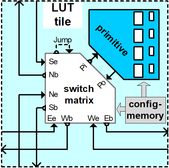
A tile is the smallest unit in a fabric and a tile provides
A description of Wires to adjacent tiles
A central Switch matrix
An optional list of Primitives
A central configuration storage module
A tile typically hosts primitives like a CLB with LUTs or an I/O block. Multiple smaller tiles can be combined into Supertiles to accomodate complex blocks like DSPs. Each tile that is referred to in the Fabric layout requires specification of the corresponding tile description in the fabric.csv file that has the following format:
TILE, LUT4AB      # define tile name
#direction  source_name  X-offset  Y-offset  destination_name  wires
NORTH,      N1BEG,       0,        1,        N1END,            4
EAST,       E2BEG,       1,        0,        N2END,            6
JUMP,       J_BEG,       0,        0,        J_END,            12
...
#         RTL code                     optional prefix
BEL,      LUT4c_frame_config_OQ.vhdl,  LA_
BEL,      LUT4c_frame_config_OQ.vhdl,  LB_
...
MATRIX,   LUT4AB_switch_matrix.list
EndTILE
Wires
Wires are defined by 5-tuples:
direction, source_name, X-offset, Y-offset, destination_name, wires
specifying:
direction,[NORTH|EAST|SOUTH|WEST|JUMP]The keyword
JUMPspecifies a stop-over at the switch matrix, which is a logical wire that starts and ends at the same switch matrix (i.e.X-offset= 0 andY-offset= 0).Jump wires are useful to model hierarchies, some sharing of multiplexers or tapping into routing paths, as shown in the examples below.
In the VPR and Altera world, tiles separate between a connection switch matrix and the actual local wire switch matrix. The connection switch matrix is nothing else as a bank of multiplexers selecting from the local routing wires a pool of connection wires that can then be further routed to primitive pins (e.g, a LUT input). In FABulous, those connection wires would be modelled with a set of jump wires, which connect then somehow to the primitive input multiplexers.
Older Xilinx architectures have a less hierarchical routing graph and local routing wires between the tiles connect directly to the input multiplexers of the primitives.
Xilinx Virtex-5 FPGAs provide diagonal routing wires (e.g., a wire routing in north-east direction), a concept abandoned in consecutive Xilinx FPGA families. FABulous can model diagonal routing by splitting a wire in its components (e.g., a north-east wire can be modeled by cascading a north wire and an east wire).
source_name,stringdestination_name,stringThese are symbolic names for the ports used for the tile top wrapper and the switch matrix connections. It is recommended to follow a semantic that expresses the direction, routing span (i.e. how many tiles far away the wire is spanning) and if it is a begin or end or other port. For instance, a single wire in NORTH direction should use names such as N1Beg to N1End or N1b to N1e.
The destination name refers to two ports: a port on the target tile and an expected port on the destination tile. This reflects that wires route between tiles and that the begin and end ports of a tile connect to different wires. However, while this works for tiles inside the fabric (like CLBs), the tiles at the border do usually not extend to antennae outside the fabric but instead route wires back into the fabric as shown in the following figure:
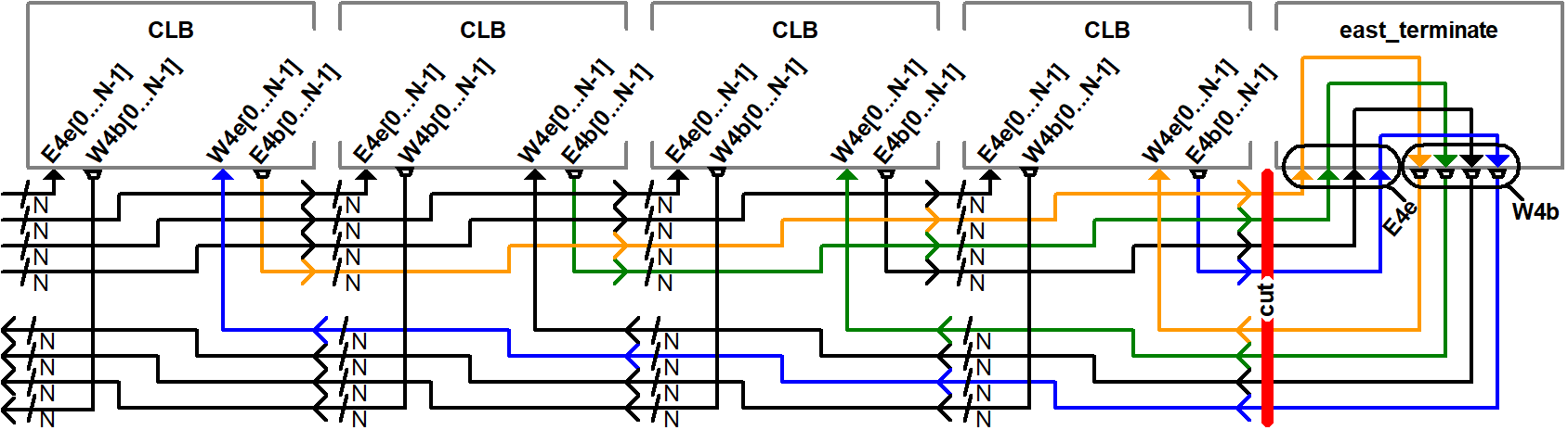
The figure illustrates how horizontal quad wires (that route 4 tiles far) are terminated at the east border of the fabric. The example follows the method used by Xilinx to terminate wires at the border of the chip. FABulous can implement this scheme, but also any other, including some extra switching at the fabric borders and providing some primitives.
The figure shows that each CLB tile has a pair of input and output ports for the two east and west directions while the east_terminate tile only has an east end port and a west begin port. Moreover, the figure shows the nested routing for long distance wires (see also the wires bullet below). It can be seen that the CLBs route through long distance wires (here quad wires) while the east_terminate tile has all internal wires connected to the switch matrix. Note that this is only an abstract view and the wires that route through the CLBs may still be buffered inside the CLB tiles. However, this is transparent from the user and not included in the architecture graph.
The shown wires in the CLBs (from the last figure) are modelled as:
# this is for the CLBs in the example
    #direction  source_name  X-offset  Y-offset  destination_name  wires
EAST,       E4b,         4,        0,        E4e,              N    # N is used for illustration only
WEST,       W4b,         -4,       0,        W4e,              N    # N is used for illustration only
To control the different behavior for tiles that do not extend a wire (as done in the terminate tiles), we use the
NULLport name for wire begin or end ports that should not be generated on the tile:# this is for the east_terminate tile in the example #direction source_name X-offset Y-offset destination_name wires EAST, NULL, 4, 0, E4e, N # N is used for illustration only WEST, W4b, -4, 0, NULL, N # N is used for illustration only
The
NULLport entry for the EAST source_name and the WEST destination_name will prevent FABulous from creating the corresponding tile port names. Moreover, theNULLport entries also will tell FABulous to connect all wires of the corresponding entry, including the nested ones, to the switch matrix. This allows the implementation of the shown U-turn routing scheme for termination but also any other more sophisticated termination scheme.For instance, in the FlexBex project, a FABulous eFPGA was coupled with the Ibex RISC V core for custom instruction set extensions (where the eFPGA fabric operates logically in parallel to the ALU) as shown in the following figure:
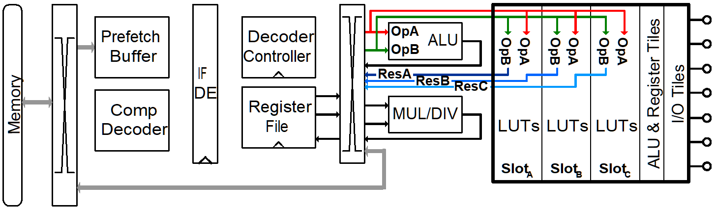
In this example, the CPU interface is located at the west border of the fabric. The fabric provides three slots, each being two CLB columns wide. The operands are routed into the fabric using double wires (so, each slot receives the operands at exactly the same position, which makes modules relocatable among the slots). The results are routed to the CPU using nested hex wires (again resulting in a homogeneous routing scheme that enables module relocation). The CPU therefore has access to the results of each slot and will multiplex results into the register file in case a custom instruction requires it to do so. For simplicity, the figure does not show the west termination tiles, which simply connect the internal routing wires to the top-level fabric wrapper that, in turn, is used to connect to the CPU. In summary, the example shows how a termination tile can be used to provide more complex interface blocks and all this can be easily modelled and implemented with FABulous.
Note
The
destination_nameis refering to the port name used at the destination tile. FABulous will throw an error if the destination tile does not provide that port name.X-offset,signed_intY-offset,signed_int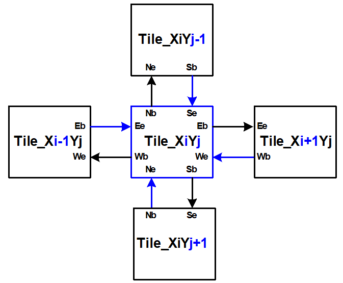
FABulous models wires strictly in horizontal or vertical direction but never directly in diagonal direction - this directly reflects the tiled physical implementation of the fabric. Therefore, in each wire specification, either
X-offsetis0orY-offsetisX-offsetor both are0(in the case of a JUMP wire).Note
The
directionfield and the sign of theX-offsetandY-offsetvalues are redundant. FABulous uses internally the absoluteX-offsetandY-offsetvalues and only thedirectionfield for specifying the direction of a wire. However, FABulous will throw a warning if there is a mismatch with the sign.wires,unsigned_intSpecifies the number of wires.FABulous will index the wires of each entry starting from [0].
A metric that is important for FPGA ASIC implementations is the channel cut number, which denotes the number of wires that must be accomodated between two adjacent tiles. The cut number is an indicator for the congestion to be expected when stitching together the fabric. Let us take the following example:
TILE, Example_tile      # define tile name
#direction  source_name  X-offset  Y-offset  destination_name  wires
EAST,       E1Beg,       1,        0,        E1End,            6
WEST,       W4Beg,       -4,       0,        W4End,            3
The following figure shows the corresponding wiring between the tiles. Note that a wire with a span greater 1 is usually nested.

Each entry in the wire specification contributes with max(abs(X-offset),abs(y-offset)) x wires to the cut number.
In this example, the east single wire (E1Beg) is contributing with 1 x 6 = 6 and the west quad wire (W4Beg) with 4 x 3 = 12 wire segments to the cut.
Therefore, even if we have only half the number of quad wires, these contribute double the number of ASIC routing tracks to the cut.
Furthermore, the wires needed to write the configuration into the configuration memory cells are further contributing substantially to the cut (see parameter FrameBitsPerRow in section Fabric CSV description).
The switch matrices see only the wires amount of wires, regardless of the span. However, the tile-to-tile interfaces include all nested wires concatenated together to a wide vector. FABulous connects the wires LSBs to the switch matrix inputs and the switch matrix outputs are connected to the wires MSBs. Inside the tile, the wide vector is shifted by wires before routing it to the next tile, as shown in the following figure for an EAST hex-wire example:
TILE, CLB
#direction  source_name  X-offset  Y-offset  destination_name  wires
EAST,       E6B,         6,        0,        E6E,              2

Note
A typical CLB requires about 100 to 200 wire connections between adjacent tiles (about 400 to 800 wires in total per tile).
The shift register configuration mode needs fewer wire connections than frame-based configuration at the tile border but shift register mode tends to have a slightly higher congestion inside the tiles because of the long chain.
Note
Because long distance wires contribute heavily to the cut number, it can be beneficial to segment long distance wires to better balance between the silicon core area and the available metal stack for implementing the routing.
Switch matrix
FABulous usually implements all routing in a central switch matrix. The inputs to the switch matrix are the wire end ports of the local wires and JUMP wires and the outputs of the Primitives. Hierarchies in an FPGA architecture graph will usually be modelled through JUMP wires (as shown in the Tiles figure). However, while it is possible to have multiple switch matrices in a tile, this is not recommended.
Configurable connections are defined in either an adjacency list or an adjacency matrix.
Adjacency list files follow the naming convention <tile_descriptor>_switch_matrix.list (e.g., LUT4AB_switch_matrix.list).
A switch matrix entry is specified by a line <output_port>,<input_port>. For convenience, it is possible to specify multiple ports though a list operator [item1|item2|…]. For instance, the following line in a list file
[N|E|S|W]2BEG[0|1|2],[N|E|S|W]2END[0|1|2] # extend double wires in each direction
is equivalent to
N2BEG0,N2END0 # extend double wires in each direction
E2BEG0,E2END0 # extend double wires in each direction
S2BEG0,S2END0 # extend double wires in each direction
W2BEG0,W2END0 # extend double wires in each direction
N2BEG1,N2END1 # extend double wires in each direction
E2BEG1,E2END1 # extend double wires in each direction
S2BEG1,S2END1 # extend double wires in each direction
W2BEG1,W2END1 # extend double wires in each direction
N2BEG2,N2END2 # extend double wires in each direction
E2BEG2,E2END2 # extend double wires in each direction
S2BEG2,S2END2 # extend double wires in each direction
W2BEG2,W2END2 # extend double wires in each direction
The example shows how port names can be composed from string segments that can alternatively be provided in list form. The lists will be recursively unwrapped, which allows it to use multiple list operators together.
An error message is generated if the number of composed port names differs for the number of input_ports and output_ports or if ports are not found. A warning will be generated if FABulous tries to set a connection that has already been specified.
A switch matrix multiplexer is modelled by having multiple connections for the same <output_port>. For example, a MUX4 can be modelled as:
N2BEG0,N2END3 # cascade and twist wire index
N2BEG0,E2END2 # turn from east to north
N2BEG0,S2END1 # U-turn
N2BEG0,LB_O   # route LUT B output north

# the same in compact form:
N2BEG[0|0|0|0],[N2END3|E2END2|S2END1|LB_O]
Adjacency lists are better for specifying and maintaining the connections while an adjacency matrix is better for monitoring and debug. FABulous works on adjacency matrices and the tool can translate arbitrarily between both. Adjacency matrix files are csv files and follow the naming convention <tile_descriptor>_switch_matrix.csv (e.g., LUT4AB_switch_matrix.csv). The following figure shows a list file and the corresponding adjacency matrix:
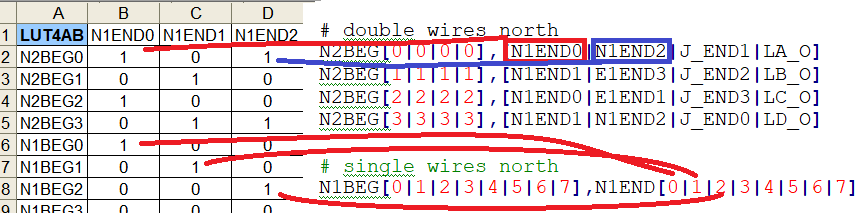
The adjacency matrix states the tile identifier name in the top left cell.
The columns denote the input ports to the switch matrix and the rows denote the output ports.
A 1 in the matrix denotes a configurable connection (i.e. a multiplexer input connection) and each 1 corresponds to a <output_port>,<input_port> tuple defined in the adjacency list.
Therefore, each row corresponds to one switch matrix multiplexer.
When generating the adjacency matrix, FABulous will annotate for each row and column the number of connections set. For the rows, this denotes the size of the multiplexers (e.g., MUX4) and by checking the column summary, we can inspect how well the wire usage is balanced.
Note
Note that we can define the port names VCC and GND in Wires, which allows it to specify a configurable multiplexer setting to 1 or 0. For instance, this is useful for BRAM pins where unused ports (e.g., some MSB address bits) have to be tied to 0 without the need of any further LUTs or routing.
#direction  source_name  X-offset  Y-offset  destination_name  wires
JUMP,       NULL,        0,        0,        GND,              1
JUMP,       NULL,        0,        0,        VCC,              1
Note
The multiplexers in the switch matrices are controlled by configuration bits only.
The multiplexers in Primitives can either be controlled by configuration bits (e.g., to select if a LUT output is to be routed to a primitive output pin or through a flop) or by the user logic (e.g., to cascade adjacent LUTs for implementing larger LUTs (like the F7MUX and F8MUX multiplexers in Xilinx FPGAs with LUT6).
Note
Defining the adjacency of a switch matrix (and the wires) is a difficult task. Too many connections and wires are expensive to implement and will result in poor density and potentially in poor performance. However, too few connections and wires may lead to an inability to implement the intended user circuits on the fabric in the first place. The latter issue is not easily solvable by leaving primitives unused because that requires, for example, the use of more CLBs. That, in turn, requires more wires between the tiles, and will therefore jeopardize the approach of underutilising the CLBs.
Another difficulty is setting good switch matrix connections. An architecture graph should have sufficient entropy because of the usual sparsity of the graph. For instance, if we have to route from a LUT to a specific DSP pin, and the first path is not hitting that pin, then using an alternative path should result in possible connections to a different subset of pins. This implies that the architecture graph should not state linear combinations in subgraphs. However, adjacent LUT inputs often share the same signal (e.g., when cascading two LUT6 to form one LUT7, the two LUT6s connect to the same 6 signals). This can be used to share some multiplexing in the switch matrices.
To simplify the definition of fabrics, the provided FABulous reference fabrics have been confirmed to implement non-trivial user circuits like different CPU cores. The provided switch matrices can be easily reused in new custom tiles (it is standard to have mostly identical switch matrices throughout an FPGA fabric, even if resources (LUTs, BRAMs, DSPs) differ). Moreover, downstripping the routing fabric is easily possible by removing wires and connections.
Primitives
Primitives are used to manipulate, store and input/output data. Examples for primitives include LUTs, slices (a cluster of LUTs that share a clock and that can be cascaded for arithmetic), flip flops, individual gates or multiplexers, and complex blocks like DSPs, ALUs or BRAMs. A tile may have no primitives (e.g., the north and south terminate tiles in our example fabric) or as many as needed.
Primitives are added with BEL statements (BEL stands for Basic Element of Logic and the phrase is adopted from Xilinx), as shown in the following tile definition fragment:
TILE, LUT4AB      # explained in subsection Tiles
#direction  source_name  X-offset  Y-offset  destination_name  wires
NORTH,      N1BEG,       0,        1,        N1END,            4
...
# bel keyword     RTL code         optional prefix
BEL,              LUT4.vhdl,       LA_
BEL,              LUT4.vhdl,       LB_
...
MATRIX,           LUT4AB_switch_matrix.vhdl
EndTILE
FABulous simply adds primitives as RTL code blocks. This is a different philosophy than the usual VPR approach where primitives are generated by models. While the VPR path has advantages to drive automated design space exploration, the FABulous way is more convenient when modeling an existing fabric. However, this requires some adaptations to the FPGA CAD tools as described in TODO. Complex blocks are usually not inferred by VHDL or Verilog constructs but through direct primitive instantiations, which is common for all commercial FPGAs. Nevertheless, Yosys can implement arrays specified in RTL automatically to BRAMs and the Verilog multiply operator directly to our DSP blocks.
The BEL statements in the previous example instantiate a LUT4 in VHDL:
entity LUT4 is
 Generic ( NoConfigBits : integer := 18 );   -- has to be adjusted manually
 Port (      -- IMPORTANT: this has to be in a dedicated line
     I0      : in    STD_LOGIC; -- LUT inputs
     I1      : in    STD_LOGIC;
     I2      : in    STD_LOGIC;
     I3      : in    STD_LOGIC;
     O       : out   STD_LOGIC; -- LUT output (combinatorial or FF)
     Ci      : in    STD_LOGIC; -- carry chain input
     Co      : out   STD_LOGIC; -- carry chain output
     UserCLK : in    STD_LOGIC; -- EXTERNAL -- SHARED_PORT
     -- the # EXTERNAL keyword will send this signal all the way to top and
     -- #SHARED allows multiple BELs using same port (exports 1 clock to top)
     ConfigBits : in          STD_LOGIC_VECTOR( NoConfigBits -1 downto 0 )
     );
end entity LUT4;
And the equivalent in Verilog:
module LUT4c_frame_config ( I0, I1, I2, I3, O, Ci, Co, SR, EN, UserCLK, ConfigBits );
  parameter NoConfigBits = 19 ; // has to be adjusted manually
  input I0; // LUT inputs
  input I1;
  input I2;
  input I3;
  output O; // LUT output ( combinatorial or FF )
  input Ci; // carry chain input
  output Co; // carry chain output
  input SR; // SHARED_RESET
  input EN; // SHARED_ENABLE
  (* FABulous, EXTERNAL, SHARED_PORT *) input UserCLK;
  // EXTERNAL keyword will send this signal all the way to the top
  // SHARED Allows multiple BELs using the same port (e.g. for exporting a clock to the top)
  // GLOBAL all primitive pins that are connected to the switch matrix have to go before the GLOBAL label
  (* FABulous, GLOBAL *) input [NoConfigBits-1 : 0] ConfigBits;
  ...
endmodule
FABulous defines the following coding rules for BELs:
Each primitive has to specify the number of configuration bits used in a generic/parameter called
NoConfigBits. This also holds if no configuration bits are used (NoConfigBits := 0).The port declarations have to be formatted to provide one declaration per line.
We use directives (provided as comments) to control the code generation semantics. The supported directives include:
EXTERNAL: ports flagged with this directive are not connected to the switch matrix but are exported through the tile entity to the top-level fabric wrapper. The corresponding port will be exported with a tile prefix and, if provided in the BEL statement, the instance prefix. The following two blocks provide an OutBlock tile with two BEL statements and the corresponding Out_Pad module:TILE, OutBlock # explained in subsection Tiles ... # bel keyword RTL code optional prefix BEL, tristate_pin.vhdl, A_ BEL, tristate_pin.vhdl, B_
entity Out_Pad is
  Generic ( NoConfigBits : integer := 0 ); -- has to be adjusted manually
  Port (      -- IMPORTANT: this has to be in a dedicated line
    I     : in    STD_LOGIC; -- LUT inputs
    O_pin : out   STD_LOGIC; -- EXTERNAL
    );
end entity Out_Pad;
If the provided RTL code are Verilog
module Out_Pad (I0, O_pin);
  parameter NoConfigBits = 19 ; // has to be adjusted manually
  input I; // LUT inputs
  (* FABulous, EXTERNAL *) output O_pin;
  ...
endmodule
In this example, the O_pin is flagged
EXTERNALand the port will therefore appear in the top fabric wrapper as:entity eFPGA is Generic ( MaxFramesPerCol : integer := 20; FrameBitsPerRow : integer := 32; NoConfigBits : integer := 0 ); Port ( -- for the first exported port: -- the tile prefix is "Tile_X0Y1", -- the BEL instance prefix is "_A" and -- the pin name is "O_pin" Tile_X0Y1_A_O_pin : out STD_LOGIC; -- EXTERNAL Tile_X0Y1_B_O_pin : out STD_LOGIC; -- EXTERNAL Tile_X0Y2_A_O_pin : out STD_LOGIC; -- EXTERNAL Tile_X0Y2_B_O_pin : out STD_LOGIC; -- EXTERNAL ... ); end entity Out_Pad;
If generating for Verilog output
module eFPGA
#(
  parameter MaxFramesPerCol=20,
  parameter FrameBitsPerRow=32,
  parameter NoConfigBits=0
)
(
  output Tile_X0Y1_A_O_pin,
  output Tile_X0Y1_B_O_pin,
  output Tile_X0Y2_A_O_pin,
  output Tile_X0Y2_B_O_pin
)
...
endmodule
TODO
SHARED_PORT: this directive can only be used together optionally withEXTERNAL. If a port is setEXTERNALbut notSHARED_PORT, then , a TODO ( shared ports flagged with this directive are not connected to the switch matrix but are exported through the tile entity to the top-level fabric wrapper.
Bitstream remapping
FABulous will take care when implementing the configuration logic and bitstream encoding and the mapping of this into configuration bitstreams. This can be done automatically. However, users can influence the mapping of configuration bits into the bitstream. For our first chip, we used remapping to create a human readable bitstream which is more convenient to modify in a hex editor, as described later in this subsection.
In the code example for a LUT, it was shown that the configuration bits are exported into the LUT interface:
entity LUT4 is
 Generic ( NoConfigBits : integer := 18 );   -- has to be adjusted manually
 Port (      -- IMPORTANT: this has to be in a dedicated line
 ...
 ConfigBits : in      STD_LOGIC_VECTOR( NoConfigBits -1 downto 0 )  -- These are the configuration bits
Exporting configuration bits is a requirement for any primitive or switch matrix that uses configuration bits. The tile configuration bitstream is formed by concatenating first the primitive configuration bits (if primitives are available and use configuration bits) and then the switch matrix configuration bits (again, only if the switch matrix uses configuration bits) into one long tile configuration word.
This is done in the order that the primitives are declared by BEL entries in the tile definition. Configuration bitstream vectors are defined in the downto direction and the first BEL primitive configuration bits will be placed at the LSB side of the tile bitstream and the configuration switch matrix at the MSB side.
Using the shift-register configuration mode will form a tile configuration chain. FABulous only supports one long bit-serial configuration chain. While configuration speed could possibly be boosted by using multiple parallel (and correspondingly shorter) chains, we have not added further optimizations, because shift register configuration is inferior to frame-based configuration mode.
For frame-based configuration mode, FABulous will pack those configuration bits into frames. By default, FABulous will start with frame 0 and pack the first FrameBitsPerRow bits from the tile configuration bitstream starting with the MSBs of the tile bitstream frame-by-frame until all configuration bits are packed. This may leave some of the FrameBitsPerRow x MaxFramesPerCol possible configuration bits unused.
FABulous is recording the bitstream mapping file (in CSV format) that follows the naming convention <tile_descriptor>_ConfigMem.init.csv (e.g., LUT4AB_ConfigMem.init.csv). The file has MaxFramesPerCol lines (one per configuration frame, which includes empty frames). A line has the format:
<frame_name>, <frame_index>, <bits_used>, <used_bits_mask>, <ConfigBits_ranges>
Where the fields mean:
<frame_name> is a symbolic name for a frame which is not further used internally by FABulous.
<frame_index> is indexed 0 to
MaxFramesPerCol-1.<bits_used> denotes the number of bits that are used in this frame and must be in the range 0 to
FrameBitsPerRow.<used_bits_mask> denotes which bits in a frame will be used. The bitmask is defined MSBs downto LSBs and a
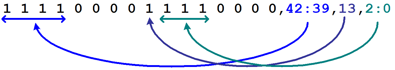
1denotes a used configuration bit, while a0denotes a gap bit that will not be used. Note that FABulous will not generate a configuration latch for those gap bits. Again, in frame-based reconfiguration, not all possibleFrameBitsPerRowxMaxFramesPerColbits will usually be used and the bitmask specifies the used and unused bits. The number of1entries per frame is redundant to <bits_used>. FABulous will count the1entries and use that value while <bits_used> is used for checking only.<ConfigBits_ranges> denotes a comma-separated list of configuration bits (given by their index) from the tile bitstream. The field can be individual bits or ranges of tile bitstream bits in the form <left_index>:<right_index>. The number of specified bits has to match the number of used configuration bits as specified by the mask and the mapping is performed in the order the configuration bits are listed, as illustrated in the following figure:
The following example is the FABulous-generated mapping file of the CLB implemented for our first FABulous TSMC chip.
frame_name,  frame_index, bits_used, used_bits_mask,                          ConfigBits_ranges
frame0,      0,           32,        1111_1111_1111_1111_1111_1111_1111_1111, 537:506
frame1,      1,           32,        1111_1111_1111_1111_1111_1111_1111_1111, 505:474
frame2,      2,           32,        1111_1111_1111_1111_1111_1111_1111_1111, 473:442
frame3,      3,           32,        1111_1111_1111_1111_1111_1111_1111_1111, 441:410
frame4,      4,           32,        1111_1111_1111_1111_1111_1111_1111_1111, 409:378
frame5,      5,           32,        1111_1111_1111_1111_1111_1111_1111_1111, 377:346
frame6,      6,           32,        1111_1111_1111_1111_1111_1111_1111_1111, 345:314
frame7,      7,           32,        1111_1111_1111_1111_1111_1111_1111_1111, 313:282
frame8,      8,           32,        1111_1111_1111_1111_1111_1111_1111_1111, 281:250
frame9,      9,           32,        1111_1111_1111_1111_1111_1111_1111_1111, 249:218
frame10,     10,          32,        1111_1111_1111_1111_1111_1111_1111_1111, 217:186
frame11,     11,          32,        1111_1111_1111_1111_1111_1111_1111_1111, 185:154
frame12,     12,          32,        1111_1111_1111_1111_1111_1111_1111_1111, 153:122
frame13,     13,          32,        1111_1111_1111_1111_1111_1111_1111_1111, 121:90
frame14,     14,          32,        1111_1111_1111_1111_1111_1111_1111_1111, 89:58
frame15,     15,          32,        1111_1111_1111_1111_1111_1111_1111_1111, 57:26
frame16,     16,          26,        1111_1111_1111_1111_1111_1111_1100_0000, 25:0
frame17,     17,          0,         0000_0000_0000_0000_0000_0000_0000_0000,
frame18,     18,          0,         0000_0000_0000_0000_0000_0000_0000_0000,
frame19,     19,          0,         0000_0000_0000_0000_0000_0000_0000_0000,
FABulous are will generate a default <tile_descriptor>_ConfigMem.csv, and users are not required to modify the <tile_descriptor>_ConfigMem.csv file. However, if FABulous finds a file called <tile_descriptor>_ConfigMem.csv before generating it, it will use the bitstream mapping provided instead. The following example shows the basic idea that was used to provide a human-readable bitstream encoding. It is not intended to understand the example in detail. The basic idea is to align configuration LUT function tables, settings and the switch matrix multiplexer encoding to be nibble aligned such that they are easy to find in a hex editor. For instance, in the example below, the first 8 frames are mostly encoding the LUTs where the 16 MSBs are the LUT tables and the next two nibbles are encoding a flop and carry-chain mode:
frame_name, frame_index, bits_used_in_frame, used_bits_mask, ConfigBits_ranges
frame0,0,32,1111_1111_1111_1111_0001_0001_0001_0001,15:00,16,17,144,145
frame1,1,32,1111_1111_1111_1111_0001_0001_0000_0000,33:18,34,35
frame2,2,32,1111_1111_1111_1111_0001_0001_0011_0011,51:36,52,53,515:514,517:516,#,J_l_CD_BEG0,J_l_CD_BEG1
frame3,3,32,1111_1111_1111_1111_0001_0001_0011_0011,69:54,70,71,519:518,521:520,#,J_l_CD_BEG2,J_l_CD_BEG3
frame4,4,32,1111_1111_1111_1111_0001_0001_0011_0011,87:72,88,89,523:522,525:524,#,J_l_EF_BEG0,J_l_EF_BEG1
frame5,5,32,1111_1111_1111_1111_0001_0001_0011_0011,105:90,106,107,527:526,529:528,#,J_l_EF_BEG2,J_l_EF_BEG3
frame6,6,32,1111_1111_1111_1111_0001_0001_0011_0011,123:108,124,125,531:530,533:532,#,J_l_GH_BEG0,J_l_GH_BEG1
frame7,7,32,1111_1111_1111_1111_0001_0001_0011_0011,141:126,142,143,535:534,537:536,#,J_l_GH_BEG2,J_l_GH_BEG3
#,E6BEG0   ,E6BEG1   ,W6BEG0   ,W6BEG1   ,JN2BEG0  ,JN2BEG1  ,JN2BEG2  ,JN2BEG3
frame8,8,32,1111_1111_1111_1111_1111_1111_1111_1111,173:170,177:174,205:202,209:206,381:378,385:382,389:386,393:390
#,JN2BEG4  ,JN2BEG5  ,JN2BEG6  ,JN2BEG7  ,JE2BEG0  ,JE2BEG1  ,JE2BEG2  ,JE2BEG3
frame9,9,32,1111_1111_1111_1111_1111_1111_1111_1111,397:394,401:398,405:402,409:406,413:410,417:414,421:418,425:422
...
The more important use case of bitstream remapping is to optimize the physical implementation of the configuration tiles. FABulous includes a corresponding optimizer that generates the bitstream remapping files automatically. The process is described in detail in TODO FPGA_2022_paper.
Supertiles
Supertiles are grouping together multiple basic Tiles. Basic tiles are the smallest tile exposed to users providing a switch matrix, wires to the surrounding, and usually one or more primitives (like in a CLB tile).
Supertiles are needed for blocks that require more logic and/or more wires to the routing fabric (e.g., as needed for DSP blocks). Therefore, supertiles will normally provide as many switch matrices as they integrate basic tiles. However, larger supertiles (e.g., hosting a CPU or similar) may only provide switch matrices in basic tiles located at the border of such a supertile In any case: supertiles must provide wire interfaces that match the surroundings when stitching them into a fabric.
Modelling
Supertiles are modelled from elementary tiles in a spreadsheet/csv file similar to how we model the whole FPGA fabric. Shapes can be defined arbitrary and NULL tiles can be used to skip fields. Examples:
SuperTILE, my_Z      # define supertile name
myZ_00,  NULL
myZ_01,  myZ_11
NULL,    myZ_12
EndSuperTILE         # this is case insensitive

SuperTILE, my_I      # define supertile name
my_top
my_mid
my_bot,
EndSuperTILE

SuperTILE, my_U      # define supertile name
myU_00,  NULL,    myU_20
myU_01,  NULL,    myU_21
myU_02,  myU_12,  myU_22
EndSuperTILE

Supertiles will be instantiated in the fabric (VHDL or Verilog) file, and supertiles themselves instantiate basic tiles (e.g., the ones shown in the figure). Therefore, supertiles define wires and switch matrices through their instantiated basic tiles.
Supertiles have an anchor tile, which is used to specify their position in the fabric. The anchor tile is determined by a row-by-row scan over the basic tiles and it will be the first non-NULL tile found. All other basic tiles will be placed relatively to the anchor tile. The anchor tiles in the figure above have been marked using a bold font. So far, anchor tiles are only used internally in FABulous but it is planned to allow placing supertiles through their anchor tiles in the fabric layout, rather than through their basic tiles.
If a basic tile has a border to the outside world (i.e. the surrounding fabric), the interface to that border is exported to the supertile interface (i.e. the Entity in VHDL). Those borders are marked blue in the figure above. Internal edges are connected inside the supertile wrapper according to the entire tile specification.
A basic tile instantiated in a supertile may not implement interfaces to all NORTH, EAST, SOUTH, WEST directions. For instance, a supertile may include basic terminate tiles if the supertile is supposed to be placed at the border of the fabric.
Tile ports that are declared EXTERNAL in the basic tiles will be exported all the way to the top-level, in the same wayas is done for Tiles
VHDL example:
         RES0_O0    : out   STD_LOGIC; -- EXTERNAL   port will be exported to top-level wrapper
         RES0_O1    : out   STD_LOGIC; -- EXTERNAL   port will be exported to top-level wrapper
Verilog example:
Supertile Functionality
With the instantiation of multiple basic tiles, we define mostly the part related to the routing fabric. The actual functionality of a tile can be either concentrated in one basic tile or inside the supertile wrapper or as a combination of both. The following figure shows this for a simple DSP block example:

The left example concentrates the DSP functionality in the bottom tile and is modelled as shown in the next code block. (Note the two extra NORTH and SOUTH wires that provide the connections between the DSP BEL (located bot) and the top basic tile).
TILE,       DSP_top
#direction  source   X-offset  Y-offset destination wires
NORTH,      N1BEG,   0,        1,       N1END,      4
# connect prmitive outputs to routing fabric
NORTH,      NULL,    0,        1,       bot2top,    10 # no route to north
EAST,       E1BEG,   1,        0,       E1END,      4
SOUTH,      S1BEG,   0,        -1,      S1END,      4
# send data from routing fabric to primitive
SOUTH,      top2bot, 0,        -1,      NULL,       18 # no route from north
WEST,       W1BEG,   -1,       0,       W1END,      4
JUMP,       J_BEG,   0,        0,       J_END,      8
MATRIX,     DSP_top_switch_matrix.vhdl
EndTILE

TILE,       DSP_bot
#direction  source   X-offset  Y-offset destination wires
NORTH,      N1BEG,   0,        1,       N1END,      4
# connect prmitive outputs to routing fabric
NORTH,      bot2top, 0,        1,       NULL,       10 # no route from south
EAST,       E1BEG,   1,        0,       E1END,      4
SOUTH,      S1BEG,   0,        -1,      S1END,      4
# send data from routing fabric to primitive
SOUTH,      NULL,    0,        -1,      top2bot,    18 # no route to south
WEST,       W1BEG,   -1,       0,       W1END,      4
JUMP,       J_BEG,   0,        0,       J_END,      8
BEL,        MULADD.vhdl                 # this is the actual functionality
MATRIX,     DSP_bot_switch_matrix.vhdl
EndTILE

SuperTILE   DSP  # declace supertile  (Functionality concentrated in DSP_bot)
DSP_top
DSP_bot
EndTILE
The right example provides the tile functionality in the supertile wrapper and is modelled as shown in the next code block. (Note the two wire entries with the LOCAL attribute in each basic tile to define that these wires are usable in the supertile wrapper. Furthermore, configuration bits for the DSP primitive will be provided through a ConfigBits BEL. This allows it to distribute the number of configuration bits among the basic tiles as needed. Note that configuration bits are organized at basic tile level.)
TILE,       DSP_top
#direction  source   X-offset  Y-offset destination wires
NORTH,      N1BEG,   0,        1,       N1END,      4
EAST,       E1BEG,   1,        0,       E1END,      4
SOUTH,      S1BEG,   0,        -1,      S1END,      4
WEST,       W1BEG,   -1,       0,       W1END,      4
JUMP,       J_BEG,   0,        0,       J_END,      8
LOCAL,      NULL,    0,        0,       DSP2top,    10
LOCAL,      top2DSP, 0,        0,       NULL,       18
BEL,        ConfigBits.vhdl
MATRIX,     DSP_top_switch_matrix.vhdl
EndTILE

TILE,       DSP_bot
#direction  source   X-offset  Y-offset destination wires
NORTH,      N1BEG,   0,        1,       N1END,      4
EAST,       E1BEG,   1,        0,       E1END,      4
SOUTH,      S1BEG,   0,        -1,      S1END,      4
WEST,       W1BEG,   -1,       0,       W1END,      4
JUMP,       J_BEG,   0,        0,       J_END,      8
LOCAL,      NULL,    0,        0,       DSP2bot,    10
LOCAL,      bot2DSP, 0,        0,       NULL,       18
BEL,        ConfigBits.vhdl
MATRIX,     DSP_top_switch_matrix.vhdl
EndTILE

SuperTILE   DSP     # declare supertile DSP
DSP_top
DSP_bot
BEL,        MULADD.vhdl
EndTILE